

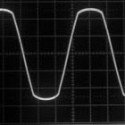
In my last few months of searching info about why my new Daiwa CN-901 meter was showing a reverse swing when my DOSY meter never showed an issue, made me start searching why. I can across a post here about Common Mode Current. Awesome! Very little information until I found the correct name for it. How a frequency wave is cut off to the point of almost a flat line. Some said it was overdriving the amp, so there is no headroom, causing the issue. but now I see there is even more to it. Oh my, I'm thinking this can get deep. Or, I am over thinking this.
But now I am really interested in how to tell if a system has it without a good meter, or does it even take a power meter/SWR problems to identify we have a CMC issue. any suggestions? Is this really "Common"?
I found this website with some interesting information from a site, (if allowed, [Please login or register to view this link] )
WHAT IS COMMON MODE CURRENT?
Common Mode Current is UNWANTED current flowing on the outer surface of the coax shield.
WHAT CAUSES COMMON MODE CURRENT?
Common Mode Current may be caused by different things:
An imbalance in the antenna system (antenna + feedline).
External signals being picked up on the shield of the coax
RFI from consumer devices
RF from other transmitters (broadcast, ham radio, anything)
OK, SO WHAT CAUSES AN IMBALANCE IN THE ANTENNA SYSTEM?
An imbalance in the antenna system can be caused by several things. We can control some of these things but often, some of the things causing the imbalance are beyond our control.
Things within our control:
Using no balun with a coax-fed balanced antenna, such as a dipole.
Using the wrong type of balun.
This is a very common cause.
Using a poor quality balun.
There are MANY of these on the market.
This is a very common cause.
Things we may not be able to control:
Objects in close proximity of our antenna, and typically closer to one side than to the other. These objects include buildings, trees, metal objects, and even other antennas.
Characteristics of the earth surrounding the antenna. In some cases it may be different on one side of the antenna than on the other.
WHAT ILL EFFECTS DOES CMC HAVE ON MY ANTENNA, MY STATION AND MY SIGNAL?
On the Antenna:
It can skew the radiation pattern.
This is especially critical with a beam (Yagi) antenna.
It can affect the SWR of the antenna.
It can cause high SWR.
It can shift the "apparent" point of minimum SWR.
It often makes SWR dependent of the length of coax.
On the Station:
It can cause RFI in the shack.
Can causes burning of the fingers on the key.
Can causes burning of the lips on the mic (Hot Lips!)
Can cause equipment such as transceivers or amplifiers to fault.
Can cause false readings on watt meters and SWR bridges.
It can cause RFI to consumer products in the house.
TVI, BCI, and interference with other consumer products.
On the Signal:
It can cause oddities on your transmitted signal
Hum, whistles, feedback and other strange noises.
It can cause a weaker transmited signal if the transceiver folds back power in the presence of SWR.
It can cause the need for a matchbox, which often eats 10+% of the power.
It can pickup noise in receive mode.
The noise can propogate all the way into the receiver, bi-passing many filters.
This is especially a problem on the low bands.
The issues of Common Mode Current and you may not know you have it.
-
hacksaw1340

- 2 PILL USER

- Posts: 19
- Joined: August 10th, 2019, 11:20 pm
- Handle: 393
- Real Name: Rik
- Radio: Cobra and kenwood
- Contact:

-
MDYoungblood
 Verified
 - Site Admin

- Posts: 10,816
- Joined: June 12th, 2010, 8:05 pm
- Handle: MDYoungblood
- Real Name: Gregory
- Antenna: HyGain AV-6160
- Radio: Icom IC-746 (non pro)
- Contact:
Re: The issues of Common Mode Current and you may not know you have it.
Thanks for the info and the link.
3's
Greg
3's
Greg
-
nosaj
- Skipshooter

- Posts: 225
- Joined: October 28th, 2018, 5:34 pm
- Handle: nosaj
- Real Name: Jason
- Radio: cobra 29 ltd
- Contact:
Re: The issues of Common Mode Current and you may not know you have it.
+1 on that. much appreciated.
nosaj
nosaj
-
Bluerunner

- Donor

- Posts: 288
- Joined: July 5th, 2013, 7:39 pm
- Handle: BlueRunner
- Real Name: Mike
- Antenna: Starduster
- Radio: Cobra 142
- Contact:
Re: The issues of Common Mode Current and you may not know you have it.
Common mode currents "CMC" can cause all kinds of problems. It will make your meters lie to you. Just put an air choke 5 turns of the feedline coax around a 4" PVC pipe piece under the antenna. I put one under the antenna and another where the coax enters my shack. No good way to identify CMC as the cause of problems unless things just get better when you eliminate it with choke coils or ferrites. 9 out of 10 times a choke fixes the problem, the 1 out of 10 that it doesn't, a second choke will fix it.
-
hacksaw1340
- 2 PILL USER
- Posts: 19
- Joined: August 10th, 2019, 11:20 pm
- Handle: 393
- Real Name: Rik
- Radio: Cobra and kenwood
- Contact:
Re: The issues of Common Mode Current and you may not know you have it.
Right on Bluerunner. I haven't built the choke yet. But I will be doing so. Easy to do as you said! I was going to try right below the feed point at the antenna and see what happens. My coax runs 10 feet down to the peak of the house then into the attic, over 50 feet then into my radio room. I hope one choke will do it for me.
-
KP68
- Skipshooter
- Posts: 401
- Joined: November 1st, 2012, 4:21 pm
- Handle: KP68
- Real Name: Ken
- Antenna: Maco M105C Mr Coily 80meter sky loop
- Radio: Apache Labs ANAN 7000DLE MKii
- Contact:
Re: The issues of Common Mode Current and you may not know you have it.
Here is a perfect example of the affects CMC can have on your equipment especially if your putting a little extra fire in the wire. Ouch! I've since subdued the problem so it's barely noticeable for now. Gotta find time to fix it properly but I'm so busy who knows when that will be. If you don't want to listen to entire gate, skip to 4:10
[Please login or register to view this link]
[Please login or register to view this link]
-
hacksaw1340
- 2 PILL USER
- Posts: 19
- Joined: August 10th, 2019, 11:20 pm
- Handle: 393
- Real Name: Rik
- Radio: Cobra and kenwood
- Contact:
Re: The issues of Common Mode Current and you may not know you have it.
Great info! wow that was really charging up the receive. I've heard it can sound like lightening static pops.. great example.. Thanks!KP68 wrote: August 14th, 2019, 9:37 am Here is a perfect example of the affects CMC can have on your equipment especially if your putting a little extra fire in the wire. Ouch! I've since subdued the problem so it's barely noticeable for now. Gotta find time to fix it properly but I'm so busy who knows when that will be. If you don't want to listen to entire gate, skip to 4:10
[Please login or register to view this link]
-
KP68
- Skipshooter
- Posts: 401
- Joined: November 1st, 2012, 4:21 pm
- Handle: KP68
- Real Name: Ken
- Antenna: Maco M105C Mr Coily 80meter sky loop
- Radio: Apache Labs ANAN 7000DLE MKii
- Contact:
Re: The issues of Common Mode Current and you may not know you have it.
No problemo. Ya gate is a little embarrassing but if will help someone see how CMC can be a big problem I don't mind at all.
-
Bluerunner
- Donor
- Posts: 288
- Joined: July 5th, 2013, 7:39 pm
- Handle: BlueRunner
- Real Name: Mike
- Antenna: Starduster
- Radio: Cobra 142
- Contact:
Re: The issues of Common Mode Current and you may not know you have it.
And anudder thing...
I find that a shorted, grounded 1/4 coax stub teed into the transmission line will solve a lot of problems like bleedover and noise too.
I find that a shorted, grounded 1/4 coax stub teed into the transmission line will solve a lot of problems like bleedover and noise too.
-
hacksaw1340
- 2 PILL USER
- Posts: 19
- Joined: August 10th, 2019, 11:20 pm
- Handle: 393
- Real Name: Rik
- Radio: Cobra and kenwood
- Contact:
Re: The issues of Common Mode Current and you may not know you have it.
Bluerunner wrote: August 14th, 2019, 12:24 pm And anudder thing...
I find that a shorted, grounded 1/4 coax stub teed into the transmission line will solve a lot of problems like bleedover and noise too.
Oh wow.. I'm thinking about that, how does it not send your RF power to the ground at that point? My mind can't figure that one out!
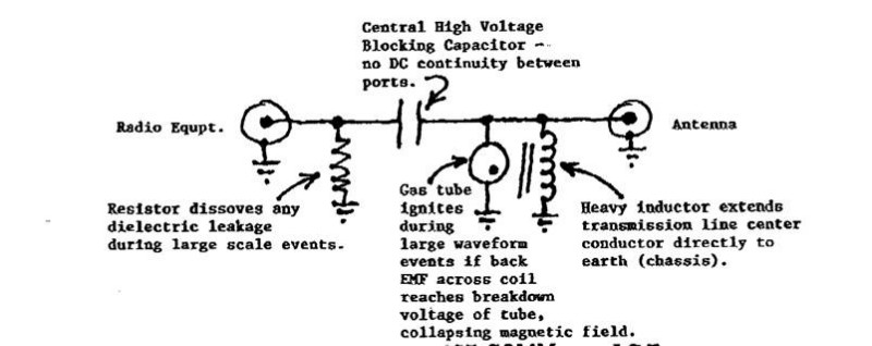
Ok so I first thought of a lightning arrestor and how are they built.. I found this and was surprised to find the antenna and feed does have points to ground,, rather through a resistor or a inducter. Interesting!
-
Bluerunner
- Donor
- Posts: 288
- Joined: July 5th, 2013, 7:39 pm
- Handle: BlueRunner
- Real Name: Mike
- Antenna: Starduster
- Radio: Cobra 142
- Contact:
Re: The issues of Common Mode Current and you may not know you have it.
I copied this from a previous post so you don't have to go looking for it. The stub shorts the center conductor to the shield and that splice can be connected to a good ground with any length of wire. Can't get better than a dead short to ground on the center conductor and shield for lightning protection.
I am a firm believer in the shorted 1/4 wave stub. I think guys may be tired of hearing about it. Often thought I should change my handle to "1/4 wave stub". Not good for multi band antennas like the hams run, but for single band CB it works like a charm.
DO NOT USE FOAM INSULATED COAX TO MAKE A STUB WITH THESE DIMENSIONS IT WON"T BE THE RIGHT ELECTRICAL LENGTH AND WILL LIKELY DAMAGE EQUIPMENT.
The measurements are critical and must be exact. Just need a coax T connector and 6' of hard Solid insulator coax with a male PL259 coax connector on one end. Measure the coax from the tip of the male PL259 and cut off the excess past 6'.
Skin back 1" of the insulation on the shield and center conductor and twist them together. I use a wire nut and add any length of single or stranded wire long enough to reach a good earth ground. The earth ground is not necessary for harmonics but it does provide a path to ground for static discharge that is more direct than through the radio chassis etc. Attach the T connector with the stub on it and the antenna coax to the amp output. Done!
It doesn't matter what kind of coax the jumpers and antenna cable is, BUT it is critical to use the solid insulator coax to make the stub, with these dimensions.
DO NOT USE FOAM INSULATED COAX TO MAKE A STUB WITH THESE DIMENSIONS IT WON"T BE THE RIGHT ELECTRICAL LENGTH AND WILL LIKELY DAMAGE EQUIPMENT.
I spent $60 for a book on such stubs. Lotsa of other kinds of stubs you can make for various purposes and fine tuning them using test equipment most CB guys don't have. I have the equipment and made a bunch of the different ones, but I found in the long run the one I described is cheap, quick, easy, works every time. It is broad band enough to work below CH1 and above CH40. It provides some out of band harmonic filtering on transmit, static discharge protection and eliminates a lot of noise from out of band harmonics and atmospheric sources on receive. All it cost is 6' of scrap coax.
I use any SOLID INSULATOR coax (.66 velocity factor) and I find that RG58 is thin enough to roll up in a coil out of the way. The only RF that goes into the stub is harmonics & noise so power handling is unimportant with modest amps. I run mine with 600 watts (i'm not one of the big dogs). The CB RF just goes right past the stub completely ignoring it. I have a stub at the radio and another at the amp output. Probably not worth the trouble, but I had two stubs and an extra T connector.
For your first stub test it on an old radio. Check the SWR with & without the stub. Should only be an insignificant change if any. I advise caution for first timers because it can be easy to mess up a measurement or incorrectly make up the PL259 connector. Holding a tape measure & floppy coax with one hand can get tricky unless you have a helper or are creative enough to anchor it down. Some of us may try to make it while "under the influence", while surfing the internet, or watching a football game or all three so caution is always advisable.
I can just feel everyone giving me the evil eye sign and hear the shuffle of feet as they run away. I just found it fascinating that putting what is essentially a dead short in your antenna system can actually improve performance and thought others may too.
If you have foam insulated coax AND KNOW WHAT ITS VELOCITY FACTOR IS you can calculate its length (246 / 27.205) X (coax velocity factor) gives the length in feet. Any coax will do, even 75 ohm TV coax for the stub but YOU MUST KNOW ITS VELOCITY FACTOR for the calculation.
-
hacksaw1340
- 2 PILL USER
- Posts: 19
- Joined: August 10th, 2019, 11:20 pm
- Handle: 393
- Real Name: Rik
- Radio: Cobra and kenwood
- Contact:
Re: The issues of Common Mode Current and you may not know you have it.
I will agree with you it is fascinating! I'm surprised in all my radio travels and discussions I've never heard of this. Thanks for posting it even with the evil eyes on ya! when I get my little test radio in, (any day now) I'll give it a try.. but I have to wash it in the dishwasher first. :D Something we just have to try!! LOL! Thank you again for the information and i look forward to trying this.
-
Bluerunner
- Donor
- Posts: 288
- Joined: July 5th, 2013, 7:39 pm
- Handle: BlueRunner
- Real Name: Mike
- Antenna: Starduster
- Radio: Cobra 142
- Contact:
Re: The issues of Common Mode Current and you may not know you have it.
I have washed circuit boards and computer keyboards in soapy water. Didn't let them soak very long. Blew the water off with compressed air and let them air dry for several days. Often works good, especially keyboards. It just has to be bone dry before you power it up. Only did it with broke or trashy looking stuff that would be no loss anyway.
-
Bluerunner
- Donor
- Posts: 288
- Joined: July 5th, 2013, 7:39 pm
- Handle: BlueRunner
- Real Name: Mike
- Antenna: Starduster
- Radio: Cobra 142
- Contact:
Re: The issues of Common Mode Current and you may not know you have it.
The CB frequencies don't even see the stub on transmit or receive. Anything that is not on the CB band sees a dead short.
This is a 1960 Popular electronics article on the shorted stub.
[Please login or register to view this link]
This is a 1960 Popular electronics article on the shorted stub.
[Please login or register to view this link]


